
Specifications
Model No. | Transmission Mode | Speed | Flow (m³/h) | Pressure (Pa) | Required Power | Power (kW) | |
4 | A | 2900 | 2198 | 3852 | 3.7 | Y132S1-2 | |
2368 | 3820 | 3.9 | |||||
2536 | 3765 | 4.1 | |||||
2706 | 3684 | 4.4 | |||||
2877 | 3607 | 4.6 | |||||
3044 | 3502 | 4.9 | |||||
3215 | 3407 | 5.2 | |||||
4.5 | A | 2900 | 3130 | 4910 | 6.3 | Y132S2-2 | |
3407 | 4863 | 6.8 | |||||
3685 | 4776 | 72 | |||||
3963 | 4661 | 7.6 | Y160M1-2 11 (recommend) | ||||
4237 | 4545 | 8.1 | |||||
4515 | 4412 | 8.7 | |||||
4792 | 4256 | 9.2 | |||||
5 | A | 2900 | 4293 | 6035 | 10.5 | Y160M2-2 15 (recommend) | |
4706 | 5984 | 11.3 | |||||
5114 | 5869 | 12.0 | |||||
5527 | 5725 | 12.9 | |||||
5941 | 5553 | 13.8 | |||||
6349 | 5381 | 14.7 | |||||
6762 | 5180 | 15.7 | 18.5 | ||||
5.6 | A | 2900 | 6032 | 7610 | 18.5 | Y180M-2 | |
6612 | 7546 | 19.9 | |||||
7185 | 7400 | 21.2 | |||||
7766 | 7218 | 22.8 | Y200L1-2 30 (recommend) | ||||
9346 | 7000 | 24.3 | |||||
8919 | 6781 | 26.0 | |||||
9500 | 6527 | 27.7 | |||||
6.3 | A | 2900 | 8588 | 9698 | 33.3 | Y225M-2 | |
9415 | 9616 | 35.8 | |||||
10230 | 9429 | 38.3 | |||||
11056 | 9195 | 41.0 | |||||
11883 | 8915 | 43.8 | |||||
12699 | 8636 | 46.8 | Y250M-2 | ||||
13525 | 8310 | 49.9 | |||||
7.1 | D | 2900 | 12292 | 12427 | 61.8 | Y280M-2 90 (recommend) | |
13475 | 12321 | 66.4 | |||||
14643 | 12078 | 71.0 | |||||
15826 | 11776 | 76.1 | |||||
17009 | 11415 | 81.3 | |||||
18177 | 11055 | 86.8 | |||||
19360 | 10635 | 92.5 | 110 | ||||
8 | D | 2900 | 17584 | 15955 | 112.3 | Y315L-2 160 (recommend) | |
19277 | 15818 | 120.5 | |||||
20947 | 15504 | 128.9 | |||||
22640 | 15112 | 138.2 | |||||
24332 | 14644 | 147.7 | |||||
26003 | 14177 | 157.6 | |||||
27696 | 13634 | 168.0 | 200 | ||||
8 | D | 1450 | 8792 | 3834 | 14.0 | Y180M-4 | |
9639 | 3802 | 15.1 | |||||
10473 | 3729 | 16.1 | |||||
11320 | 3638 | 17.3 | |||||
12166 | 3529 | 18.5 | |||||
13001 | 3421 | 19.7 | Y180L-4 | ||||
13848 | 3294 | 21.0 | |||||
9 | D | 1450 | 12518 | 4869 | 25.3 | Y225S-4 37 (recommend) | |
13723 | 4828 | 27.2 | |||||
14913 | 4736 | 29.0 | |||||
16118 | 4620 | 31.1 | |||||
17322 | 4481 | 33.3 | |||||
18512 | 4343 | 35.5 | |||||
19717 | 4181 | 37.8 | 45 | ||||
10 | D | 1450 | 17172 | 6143 | 41.9 | Y250M-4 | |
19319 | 6056 | 46.0 | |||||
21465 | 5920 | 50.5 | |||||
23612 | 5761 | 55.3 | Y280S-4 75 (recommend) | ||||
25758 | 5560 | 60.3 | |||||
27905 | 5309 | 65.0 | |||||
30052 | 5065 | 69.6 | |||||
11.2 | D | 1450 | 24126 | 7747 | 73.8 | Y315S-4 | |
27142 | 7637 | 81.0 | |||||
30157 | 7464 | 89.0 | |||||
33173 | 7264 | 97.4 | |||||
36189 | 7009 | 106.2 | |||||
39205 | 6691 | 114.5 | Y315M-4 | ||||
42221 | 6382 | 122.7 | |||||
11.2 | D | 960 | 15973 | 3346 | 21.4 |
| |
17969 | 3299 | 23.5 | |||||
19966 | 3225 | 25.8 | |||||
21963 | 3140 | 28.3 | |||||
23959 | 3031 | 30.8 | Y250M-6 37 (recommend) | ||||
25956 | 2895 | 33.2 | |||||
27953 | 2763 | 35.6 | |||||
Show only some parameters
Product Introduction
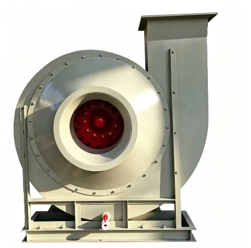
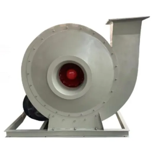
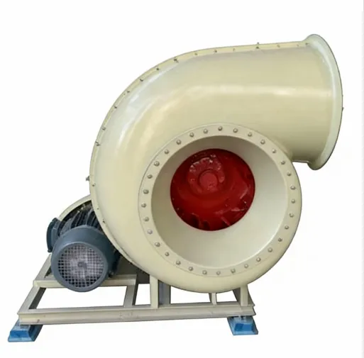
The F9-26 centrifugal induced draft fan is a purpose-built industrial ventilation unit engineered for high-static-pressure exhaust duties in corrosive, humid, or chemically aggressive environments. Its entire flow path — including the spiral volute casing, inlet cone, and impeller — is fabricated from fiberglass-reinforced plastic (FRP) using a hand lay-up and vacuum bagging process that achieves a fiber volume fraction of 40% to 48% and a void content below 0.5% by volume. The resin system is a bisphenol-A epoxy vinyl ester selected for its exceptional resistance to hydrolysis, chlorides, and oxidizing agents across a pH range of 1 to 13. The external gel coat incorporates UV stabilizers and a micronized ceramic filler to enhance abrasion resistance and maintain surface gloss under continuous outdoor exposure. The impeller employs a backward-curved blade profile with 12 blades precisely formed to maintain a chord tolerance of ±0.2 mm and a trailing edge thickness variation of less than 0.05 mm. Each impeller is dynamically balanced to ISO 1940 G2.5 grade, limiting residual unbalance to 0.3 gram-millimeter per kilogram of rotor mass. The shaft is machined from duplex stainless steel (UNS S31803) with a minimum yield strength of 450 MPa and fitted with PTFE-impregnated lip seals housed in cast iron bearing frames with regreasable labyrinth seals. The drive train supports both direct-coupled and V-belt configurations, with motor options ranging from 1.1 kW to 160 kW at IE3 or IE4 efficiency classes, enclosed to IP55 or IP56 standards. The volute cross-section expands linearly following the Archimedean spiral law, with the cutoff clearance set at 11% of impeller tip radius to optimize the trade-off between recirculation losses and tonal noise. Finite element analysis confirms that all natural frequencies of the housing and support frame lie outside the operating speed range of 580 rpm to 2950 rpm by a margin of at least 22%. The fan complies with ATEX II 2G Ex h IIC T4 Gb and IECEx standards for gas groups IIC, as well as ISO 9001:2015 quality management protocols. Each unit undergoes factory acceptance testing including airflow measurement per AMCA 210, vibration analysis per ISO 14694, dielectric strength testing at 2 kV, and pressure decay leak detection at 1.5× design pressure.
Advantages
🔹 Corrosion Resistance
Constructed from FRP (Fiber Reinforced Plastic), offering superior resistance to acids, alkalis, salts, and humid environments — ideal for chemical, marine, and wastewater applications where metal fans fail prematurely.
🔹 Non-Sparking & Explosion Safe
Impeller made from conductive resin composite; no risk of spark generation during operation. Certified for use in ATEX Zone 1, Group IIC (IEC 60079), making it safe for explosive atmospheres.
🔹 High Efficiency at Partial Load
Backward-curved blades + optimized volute design = stable airflow even under reduced load. Perfectly compatible with VFDs (Variable Frequency Drives) to cut energy consumption by up to 30%.
🔹 Low Maintenance & Long Service Life
No lubrication required; self-cleaning smooth surfaces minimize dust buildup. Modular bearing frame allows in-situ replacement — downtime reduced by 70% vs traditional designs.
🔹 Precision Balanced & Factory Tested
Dynamic balancing to ISO 1940 G2.5 standard; tested at 1.5x static pressure before shipment. Ensures quiet operation (<75 dB(A)) and vibration-free performance over 50,000+ hours.
🔹 Seamless Integration & Monitoring Ready
Optional sensors (vibration, temp, differential pressure) enable real-time condition monitoring. Compatible with BMS/BAS systems for predictive maintenance and automated alerts.
🔹 Global Compliance & Documentation
Delivered with CE, ISO 9001, and ATEX certificates. Full technical datasheet, mounting drawings, and operating manuals included — ready for international project approvals.
Applications
- 🔬 Chemical Processing Plants--Handles aggressive gases including HCl, SO₂, and Cl₂ in synthesis and storage areas. FRP construction resists acid attack and prevents metallic contamination.
- ⚓ Marine & Offshore Platforms--Withstands salt-laden air and high humidity in engine rooms and ballast water treatment zones. No galvanic corrosion — ideal for long-term sea-going service.
- 💊 Pharmaceutical Facilities--Provides solvent vapor extraction and cleanroom exhaust. Smooth, non-porous FRP surfaces prevent particle accumulation and comply with GMP cleaning protocols.
- 🚰 Wastewater Treatment Plants--Extracts odorous gases (H₂S, CH₄) from digesters and headworks. Operates continuously at elevated temperatures with high particulate loading.
- ⛽ Oil & Gas Refineries--Supports flare gas recovery and hydrocracker vent systems. Non-sparking impeller and conductive resin formulation ensure safe operation in Zone 1 explosive atmospheres.
- 🍞 Food & Beverage Processing--Exhausts steam, vapor, and acidic condensate from ovens, dryers, and sterilization tunnels. Resists corrosion where carbon steel fails within months.
- ⚡ Power Generation Plants--Integrated into flue gas desulfurization (FGD) bypass ducts. Handles hot, dusty, sulfurous gas streams while maintaining static pressure recovery.
- 🔄 Variable Frequency Drive (VFD) Compatibility--Backward-curved blade design delivers stable airflow across a wide operating range. Reduces energy consumption during partial-load conditions.
- 🔧 Modular Maintenance Design--Bearing frame can be replaced in situ without disturbing volute or ductwork connections. Minimizes downtime during scheduled maintenance.
- 📊 Real-Time Condition Monitoring--Optional vibration, temperature, and differential pressure sensors feed data into predictive maintenance platforms. Reduces unplanned failures.
- ✅ Factory Testing & Certification--Each unit undergoes dynamic balancing to ISO 1940 G2.5, static pressure test at 1.5× rated value, and dielectric strength test at 2 kV. Complies with ATEX II 2G Ex h IIC T4 Gb and IECEx standards.

F9-26 Centrifugal Induced Draft Fan | High Pressure Boiler Exhaust
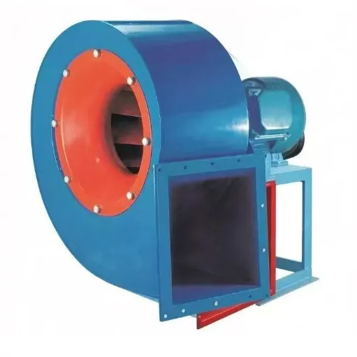
F9-26 centrifugal induced draft fan designed for high-efficiency exhaust in corrosive industrial environments. Features FRP composite construction, backward-curved blades, and IE3/IE4 motor compatibility. Ideal for chemical, marine, and pharmaceutical applications requiring corrosion resistance and minimal maintenance.