Model No. | Speed(rpm) | Pressure(Pa) | Airflow(m³/h) | Power(kw) |
6.8A | 2900 | 10523~11439 | 675~2295 | 7.5~15 |
7.1D | 2900 | 11016~12471 | 768~2919 | 5.5~18.5 |
8D | 2930 | 14277~16163 | 1110~4219 | 11~37 |
8.5D | 2950 | 17013~18496 | 1341~4560 | 15~45 |
9D | 2950 | 18318~20736 | 1591~6049 | 22~75 |
8D | 2950 | 16216~17096 | 2996~7133 | 30~55 |
9D | 2970 | 20803~21931 | 4295~9039 | 45~90 |
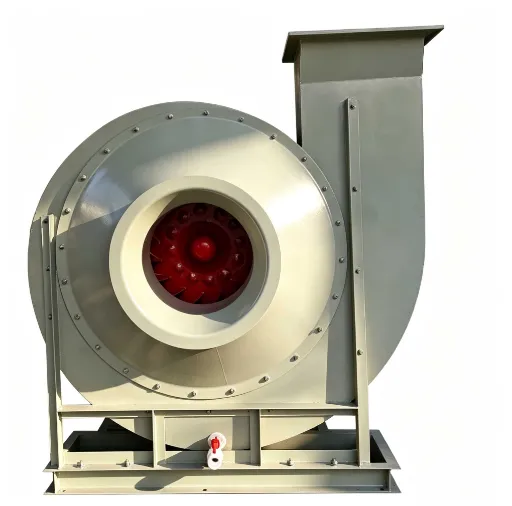
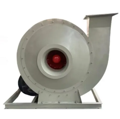
Model 9‑26 centrifugal fans are generally used for forced‑draft ventilation of forging furnaces. They are also widely applied for material conveying and delivering non‑corrosive, non‑self‑ignitable gas free of sticky substances.
The medium temperature shall generally not exceed 50℃ (max. 80℃). The dust and hard‑particle content in the medium shall be no more than 150 mg/m³.
This fan is of single‑inlet type, available in 13 sizes: No.4, 4.5, 5, 5.6, 6.3, 7.1, 8, 9, 10, 11.2, 12.5, 14, 16.
The fan can be manufactured in clockwise‑rotation (right‑hand) or counter‑clockwise‑rotation (left‑hand) configuration. Viewed from the motor side, clockwise impeller rotation stands for a right‑hand fan (marked "Right"), while counter‑clockwise rotation stands for a left‑hand fan (marked "Left").
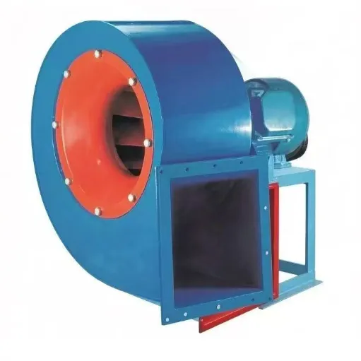
The outlet orientation is defined by the casing outlet angle. Both left‑hand and right‑hand versions can be supplied at 6 outlet angles: 0°, 45°, 90°, 135°, 180°, 225°.
Two drive arrangements are available: Type‑A (for No.4‑6.3) and Type‑D (for No.7.1‑16).
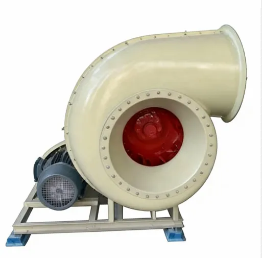
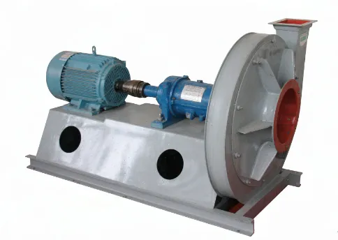
Units No.4‑6.3 mainly consist of impeller, casing, inlet nozzle and support. Units No.7.1‑16 are composed of impeller, casing, inlet nozzle and drive assembly.
(1) Impeller
The 9‑26 fan is fitted with a 16‑blade, forward‑curved impeller. The maximum peripheral speed at the outer edge of the impeller hub shall not exceed 140 m/s.
The impeller is static‑ and dynamically‑balanced after fabrication to ensure smooth operation.
(2) Casing
The volute‑shaped casing is welded from ordinary carbon‑steel plates as an integrated assembly.
(3) Inlet Nozzle
The converged streamlined integral inlet nozzle is bolted to the front cover‑plate assembly.
(4) Drive Assembly
Consists of main shaft, bearing housing and coupling. The main shaft is made of high‑quality steel. The integral bearing housing uses ball bearings lubricated with grease.
Dimension‑less performance tables and curves are provided only for the No.10 size of 9‑26 fans. Dimensional performance for other sizes can be calculated from these data.
✅ Robust High-Pressure Performance — Delivers consistent, powerful airflow under elevated static pressure, ensuring reliable operation in demanding industrial environments where standard fans fail.
🔧 Direct-Drive Design — Eliminates belts, pulleys, and alignment issues, reducing maintenance costs and downtime while increasing overall system efficiency.
🛡️ Heavy-Duty Durability — Constructed from carbon steel or stainless steel to resist corrosion, abrasion, and high temperatures — built to last in harsh conditions.
🌪️ Precision Aerodynamics — Engineered impeller blades optimize energy conversion, minimizing turbulence and maximizing volumetric efficiency for smooth, stable air delivery.
📏 Compact Footprint — Space-saving design ideal for retrofits and tight installations without sacrificing performance or airflow capacity.
⚙️ Flexible Configuration — Available in multiple sizes, motor options (IE2/IE3/IE4), and mounting configurations (base, wall, duct) to match specific system requirements.
🌍 Global Compliance — Meets or exceeds CE, ISO 9001, and ATEX standards (optional), ensuring safe, legal, and reliable operation across international markets.
💨 Low Noise Operation — Optimized casing and blade geometry reduce operational noise levels, making it suitable for urban factories, laboratories, and residential-adjacent zones.
🔄 Continuous Operation Ready — Designed for 24/7 non-stop service with thermal overload protection, vibration dampening, and sealed bearings for zero-lubrication maintenance cycles.
📈 Energy Efficiency — High static pressure capability at lower RPMs reduces power consumption compared to low-pressure alternatives, lowering long-term operational costs.
The 9-26 High Pressure Centrifugal Fan is designed for high-pressure forced ventilation in industries such as metallurgical furnaces, glass, electroplating, ceramics, batteries, and radio. It is also widely used for material conveying in processing industries like grain, feed, and mineral powder, as well as for supporting equipment such as carton machinery and tempered glass devices. The 9-19 series features a forward-curved blade design with a cantilevered impeller mounted directly on the motor shaft. Its compact structure consists of a spiral volute casing, a tapered inlet cone, and a high-strength steel plate welded base frame. The impeller undergoes strict dynamic balancing to ensure smooth operation at high rotational speeds, typically ranging from 1450 to 2900 RPM depending on the model size. This design enables the fan to generate static pressures up to 15,000 Pa while maintaining relatively stable flow characteristics, making it particularly suitable for pneumatic conveying systems and combustion air supply applications where consistent pressure output is critical.